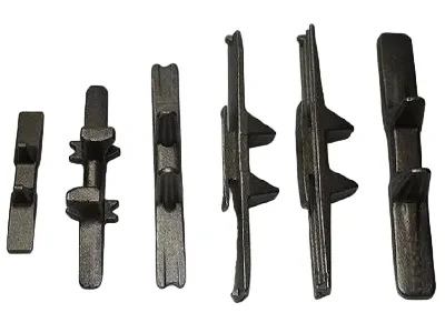
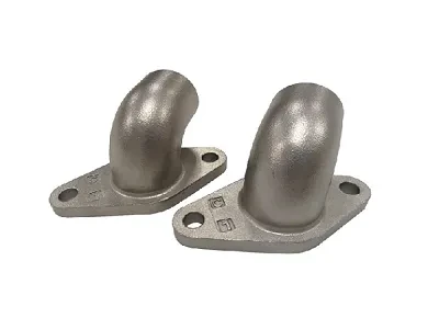
Create a sustainable future


Balasen provides custom furan resin sand castings for industrial components based on customer drawings and material requirements. We evaluate the casting route according to part geometry, casting weight, machining allowances and inspection needs. Send your drawing, material grade, estimated weight, required quantity and critical dimensions for a feasibility review and quotation.
01 / HOW THE PROCESS WORKS
Furan resin sand casting forms a mold by bonding sand with a furan-based resin system. Cores can create internal passages; after pouring and shakeout, the casting is cleaned and the specified surfaces can be machined.
For Balasen’s custom castings, the part drawing decides whether this route fits. Material grade, wall sections, internal features, casting weight and required finished condition must be reviewed together.
Start with the part: mark the bores, sealing faces and datums that need machining. The remaining surfaces can then be reviewed as cast.
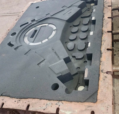
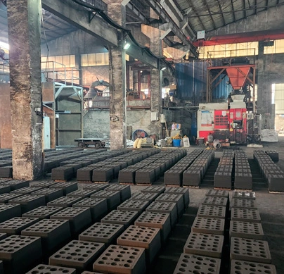
Resin sand mold from Balasen’s process imagery
02 / PROCESS FIT
The value of a stronger resin-bonded mold is most relevant when the drawing needs a considered core, mold and finishing plan. These are the questions to answer before choosing it for a specific order.
A body with an internal opening needs a practical core layout, support and cleaning route.
Weight, section changes, mold access and feeding matter more than a maximum weight figure alone.
Bores, flanges and mating faces need a defined machining allowance and final inspection basis.
Comparing this route with green sand? Read Balasen’s sand casting comparison. This page focuses on the parts Balasen can evaluate and quote.
03 / ENGINEERING REVIEW
Balasen’s page lists gray iron, ductile iron, cast steel and copper castings. A drawing review checks the exact alloy and part shape before a published process range is applied to your project.
MATERIAL ROUTE
Provide the grade and standard. Melting, solidification, any required heat treatment and inspection vary by material; one generic capability figure cannot describe them all.
PART GEOMETRY
Mark internal cavities, changes in wall thickness and difficult-to-access features. These affect the mold, feeding and cleaning plan.
Decision point: the applicable casting weight, tolerance and lead time are confirmed against the drawing, alloy and order requirements.
04 / PRODUCTION AND VERIFICATION
The mold is only one part of the result. A casting’s surface, as-cast dimensions and finished interfaces depend on decisions made before pouring and after shakeout.
01
Plan parting lines, internal passages and machining allowances from the approved drawing.
02
Assess sand condition, feeding and pouring for the chosen alloy and section thickness.
03
Define the final condition of bores, sealing faces and assembly datums separately.
04
Set measurement points, test methods and acceptance values from the purchase specification.
05 / CASTING EXAMPLES
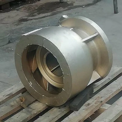
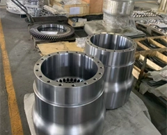
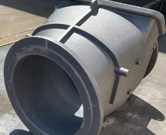
The examples below show different body shapes, internal passages and mounting features. Use your own drawing to confirm material, dimensions and the required finished condition for a comparable part.
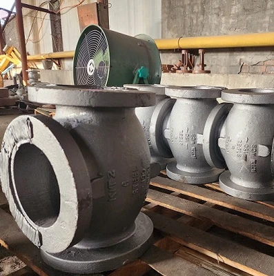
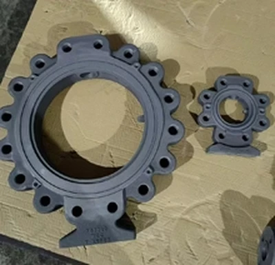
Flanged body
Internal opening and mounting flanges
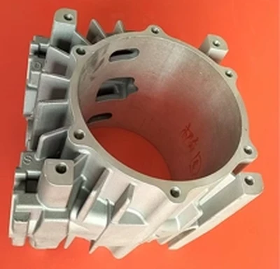
Cylindrical component
Central passage and complex inner form
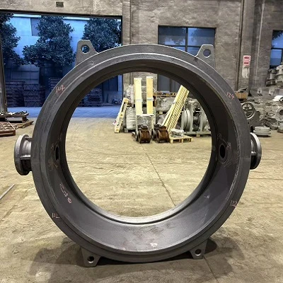
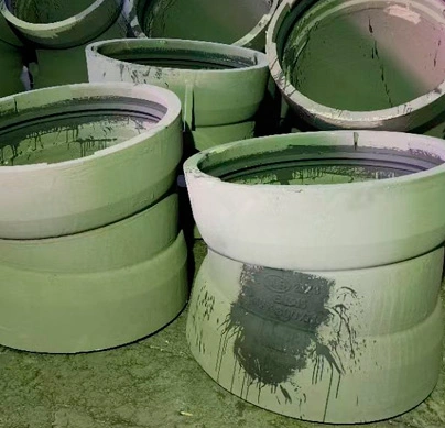
Large ring-shaped component
Large opening and external features
Have a similar part? Send the drawing with your required grade, machining areas and inspection criteria so suitability can be checked for your design.
06 / BEFORE YOU REQUEST A QUOTE
The existing upload form is directly below this section. Send the drawing and project requirements together so the proposed molding, finishing and inspection routes can be evaluated as one job.
RFQ drawing pack
Drawing revision and critical dimensions
Alloy grade, estimated weight and order quantity
Machined faces and required final surface condition
Application, inspections and delivery destination
Please upload files like drawings, material specifications, quantities, and shipping destination.
 +86-18816569813
 EN